 |
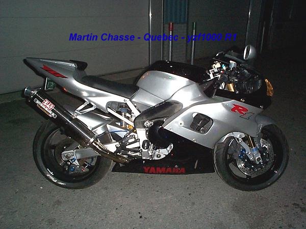
Yamaha YZF1000 R1 02-03 |
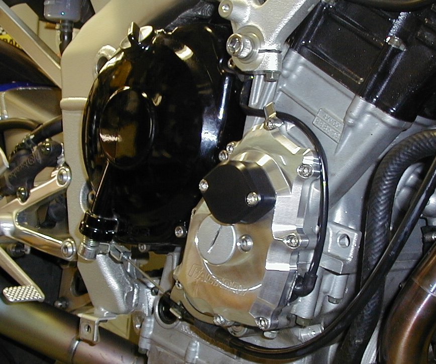
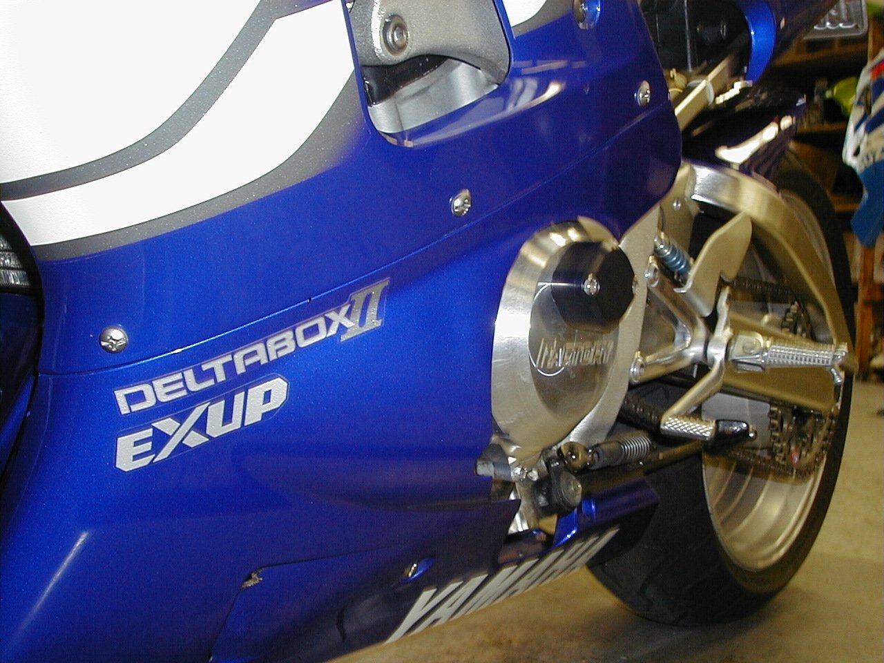
| Billet Alloy Engine Covers - now with pat pend. Integrated Frame "Sliders"! | ||
|
|
RH and LH
Billet Engine Covers with Frame
Sliders!
Check it out - Bike
tips over, off the centerstand in
your driveway.
|
|
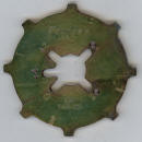
| Ignition Timing Rotors | ||
|
$99.95 |
Buy this only if you want a better running engine!
Ignition
Advance Rotor
(typical increase
|
|
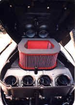
| Air Filters, Street and Race series | ||
|
|
Will
add ~1hp at high rpm when properly
tuned. Suggest cleanable BMC air filter system (avail. direct from Factory) for more power - click here / there for more information. |
|
|
|
Will
add ~1hp - 2hp at high rpm. True Rear Wheel Horsepower tm scale - difference between other scales. This filter filters as well as the STREET version - but flows more, having more filter area than the STREET filter. Cleanable BMC air filter systems (avail. direct from Factory Pro) for more power - click here for more information. Must rejet with the "Race" filter. (This IS the BEST air filter available for bets power. Marc) |
|
True Rear Wheel Horsepower tm Factory EC997
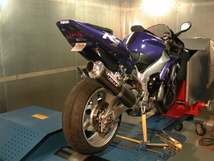
Low Inertia EC997 Eddy Current Dyno in operation in Switzerland at
Pichard Racing
For Factory Pro Tuning Center locations - click here!
Links
Misc. Information
ECU TROUBLESHOOTING CODES
With your bikes key on the off position, push the reset and select
(both buttons) for 8 seconds. Turn the key on. When it says diag. on the lcd....release
the buttons then press them again for 2 seconds. you will see a number 16 in the
lcd.
That's the throttle position indicator for #01
Code
FI FUEL INJECTION SYSTEM
Diagnostic mode table
Set the meter display from the regular mode to the diagnosis mode. For the setting
method, refer to “DIAGNOSTIC MODE”.
Listing order....
## Diagnostic type code
This test obtains this data
Actions to perform to obtain information
Actions to perform to obtain information
reference value as specced by Yamaha
reference value as specced by Yamaha
01 Throttle angle
Displays the throttle angle.
• Check with throttle fully closed.
• Check with throttle fully open. 0 ~ 125 degrees
• Fully closed position (15 ~ 17)
• Fully open position (97 ~ 100)
This test shows how the internal maps are
referenced to actual throttle position.
If the the ECU thinks that the throttle is open 96% of the way when throttle angle
is actually at a mechanical 100% throttle, if simply means that the ECU is accessing
the Main Fuel and Main Ignition map values at 96% throttle, rather than whatever
the map actually specifies for 100% throttle.
Is that a huge difference - 96% to 100%? Power Commanders don't even have a 90%
throttle position for adjustment, so, at their self proclaimed, "state of
the art", at least they don't think it's important from 81% to100%.
I don't really agree with a 19% spread as being "not important", and the TEKA EMS
has a lot better resolution or "granularity" from the bottom to the top in both
rpm and throttle position. (Whenever we release it!)
As far as the 4% difference at Full throttle of our example - the mixture and timing
differences are likely negligible and would want to see A-B-A-B testing to prove
that one - and only in Steady State test mode - to eliminate the affects of Sweep
Test fuel contamination.
Now - as far as the lower % of throttle position, things get a bit more apparent.
At smaller throttle positions, the fuel and ignition timing changes significantly
with small % changes of throttle and rpm.
If you change the Throttle Position Sensor setting, the differences are more apparent.
Moving the TPS setting, will affect the cruise, idle (and maybe - just maybe) the
cold starting.
Moving the TPS will cause the ECU to advance or retard the ignition timing, based
on it's accessing the internal ECU maps at the same SOFTWARE TPS %, which is now
related to a different MECHANICAL TB % opening.
02 Atmospheric pressure
Displays the atmospheric pressure.
* Use an atmospheric pressure gauge to check the atmospheric pressure.
Compare it to the value displayed on the meter.
This is the sensor that is supposed to help
adjust the fuel and possibly the ignition timing as related to barometric pressure
- as in 14k feet at Pike Peak or 5k feet at Colorado Springs or San Francisco at
sea level.
In "theory", the sensor works just fine, but the actual amount of compensation may
or may not have been internally "mapped" nicely, as in the 01-02 gsxr750 Suzuki's
- which had to be mapped very differently from sea level to 5k feet this year at
AMA races. The gsxr600's, however, seemed to have a better compensation map and
required negligible fuel map changes! Not picking on Suzuki - as these compensation
maps are "evolved" rather than "generated by the numbers". The 2003 and later Suzuki's
seem to be pretty spot on.
03 Pressure difference
(atmospheric pressure - intake air pressure)
Displays the pressure difference (atmospheric pressure - intake air pressure).
Engine stop switch is on.
* Generate the pressure difference by cranking the engine with the starter, without
actually starting the engine. 10 ~ 200 mmHg
Aha! This is the sensor that helps the ECU
change mapping (yes, another internal map!) as intake air pressure changes as in
ram-air and cleaner or dirtier air filters -
05 Intake temperature
Displays the intake air temperature.
* Check the temperature in the air cleaner case.
Compare it to the value displayed on the meter.
This sensor
06 Coolant temperature
Displays the coolant temperature.
* Check the temperature of the coolant.
Compare it to the value displayed on the meter.
07 Vehicle speed pulse
Displays the accumulation of the vehicle pulses that are generated when the tire
is spun.
(0 ~ 999; resets to 0 after 999)
OK if the numbers appear on the meter.
08 Lean angle cut-off switch
Displays the lean angle cut-off switch values.
Upright: 0.4 ~ 1.4 V
Overturned: 3.8 ~ 4.2 V
09 Fuel system voltage
(battery voltage)
Displays the fuel system voltage (battery voltage).
Engine stop switch is on.
0 ~ 18.7 V
Normally, approximately 12.0 V
20 Sidestand switch
Displays that the switch is ON or OFF. (When the gear is in a position other than
neutral.)
Stand retracted: ON
Stand extended: OFF
21 Neutral switch
Displays that the switch is ON or OFF
Neutral: ON
In gear: OFF
30 Ignition coil #1
After 1 second has elapsed from the time the engine stop switch has been turned
from OFF to ON, it actuates ignition coil #1 for five times every second and illuminates
the engine trouble warning light.
* Connect an ignition checker.
* If the engine stop switch is ON, turn it OFF once, and then turn it back ON.
Check that spark is generated, 5 times with the engine stop switch ON.
31 Ignition coils #2
After 1 second has elapsed from the time the engine stop switch has been turned
from OFF to ON, it actuates ignition coil #2 for five times every second and illuminates
the engine trouble warning light.
* Connect an ignition checker.
* If the engine stop switch is ON, turn it OFF once, and then turn it back ON.
Check that spark is generated, 5 times with the engine stop switch ON.
32 Ignition coil #3
After 1 second has elapsed from the time the engine stop switch has been turned
from OFF to ON, it actuates ignition coil #3 for five times every second and illuminates
the engine trouble warning light.
* Connect an ignition checker.
* If the engine stop switch is ON, turn it OFF once, and then turn it back ON.
Check that spark is generated, 5 times with the engine stop switch ON.
33 Ignition coil #4
After 1 second has elapsed from the time the engine stop switch has been turned
from OFF to ON, it actuates ignition coil #4 for five times every second and illuminates
the engine trouble warning light.
* Connect an ignition checker.
* If the engine stop switch is ON, turn it OFF once, and then turn it back ON.
Check that spark is generated, 5 times with the engine stop switch ON.
36 Injector #1
After 1 second has elapsed from the time the engine stop switch has been turned
from OFF to ON, it actuates the injector five times every second and illuminates
the engine trouble warning light.
* If the engine stop switch is ON, turn it OFF once, and then turn it back ON.
Check the operating sound of the injector five times with engine stop switch ON.
37 Injector #2
after 1 second has elapsed from the time the engine stop switch has been turned
from OFF to ON, it actuates the injector five times every second and illuminates
the engine trouble warning light.
* If the engine stop switch is ON, turn it OFF once, and then turn it back ON.
Check the operating sound of the injector five times with engine stop switch ON.
38 Injector #3
After 1 second has elapsed from the time the engine stop switch has been turned
from OFF to ON, it actuates the injector five times every second and illuminates
the engine trouble warning light.
* If the engine stop switch is ON, turn it OFF once, and then turn it back ON.
Check the operating sound of the injector five times with engine stop switch ON.
39 Injector #4
After 1 second has elapsed from the time the engine stop switch has been turned
from OFF to ON, it actuates the injector five times every second and illuminates
the engine trouble warning light.
* If the engine stop switch is ON, turn it OFF once, and then turn it back ON.
Check the operating sound of the injector five times with engine stop switch ON.
48 AI system solenoid
After 1 second has elapsed from the time the engine stop switch has been turned
from OFF to ON, it actuates the AI system solenoid five times every second and illuminates
the engine trouble warning light.
* If the engine stop switch is ON, turn it OFF once, and then turn it back ON.
Check the operating sound of the AI system solenoid 5 times with the engine stop
switch ON.
50 Fuel injection system relay
After 1 second has elapsed from the time the engine stop switch has been turned
from OFF to ON, it actuates the fuel injection system relay five times every second
and illuminates the engine trouble warning light (the light is OFF when the relay
is ON, and the light is ON when the relay is OFF).
* If the engine stop switch is ON, turn it OFF once, and then turn it back ON.
Check the fuel injection system relay operating sound 5 times with the engine stop
switch ON.
51 Radiator fan motor relay
After 1 second has elapsed from the time the engine stop switch has been turned
from OFF to ON, it actuates the radiator fan motor relay five times every 5 seconds
and illuminates the engine trouble warning light. (ON 2 seconds, OFF 3 seconds)
* If the engine stop switch is ON, turn it OFF once, and then turn it back ON.
Check the radiator fan motor relay operating sound 5 times with the engine stop
switch ON.
(At that time, the fan motor rotates.)
52 Headlight relay 1
After 1 second has elapsed from the time the engine stop switch has been turned
from OFF to ON, it actuates the headlight relay five times every 5 seconds and illuminates
the engine trouble warning light. (ON 2 seconds, OFF 3 seconds)
* If the engine stop switch is ON, turn it OFF once, and then turn it back ON.
Check the headlight relay operating sound 5 times with the engine stop switch ON.
(At that time, the headlight turns ON.)
53 EXUP servo motor
After 1 second has elapsed from the time the engine stop switch has been turned
from OFF to ON, it actuates the servo motor turns to open side at 3 seconds and
to close side at 3 seconds.
* If the engine stop switch is ON, turn it OFF once, and then turn it back ON.
Turn on the engine trouble warning light while servo motor is operated.
60 E2PROM fault code display
• Transmits the abnormal portion of the data in the E2PROM that has been detected
as a self-diagnostic fault code 44.
• If multiple malfunctions have been detected, different codes are displayed at
2-second intervals, and this process is repeated.
(01 ~ 04) Displays the cylinder number.
(00) Displays when there is no malfunction.
61 Malfunction history code display
• Displays the codes of the history of the self-diagnosis malfunctions (i.e., a
code of a malfunction that occurred once and which has been corrected).
• If multiple malfunctions have been detected, different codes are displayed at
2-second intervals, and this process is repeated.
11 ~ 50
(00) Displays when there is no
malfunction.
62 Malfunction history code erasure
• Displays the total number of codes that are being detected through self diagnosis
and the fault codes in the past history.
• Erases only the history codes when the engine stop switch is turned from OFF to
ON. If the engine stop switch is ON, turn it OFF once, and then turn it back ON.
00 ~ 21
(00) Displays when there is no
malfunction.
70 Control number
• Displays the program control number. 00 ~ 255
Stock cam timing:
intake: 102 degrees
exhaust: 103 degrees
Factory Pro V Stack set
TRUE HP: 130
Test:
Factory Pro V Stack set
BMC Race Filter
Cam Timing Specs
intake: 102 degrees
exhaust: 105 degrees
TRUE HP: 134
#38?
![[Most Recent Quotes from www.kitco.com]](http://kitco.com/images/live/s_gold.gif)
|
|||||||
| LINKS | |||||||
|
EFI and Carb Tuning - Most all
FI and carb tuning by Wheelsmith Racing |
|||||||
|
The Harringtons
own
American Flyers, one of the most
established flight training facilities
in the USA. 8 locations 800-362-0808 |
Flight Training - train with AMA race winner Todd Harrington. |
||||||
|
Insurance ONLINE QUOTE Clearinghouse Get ONLINE realtime quotes from multiple companies - One Stop MC, auto, home and more from insurance companies you know and trust. |
 |
||||||
|
|
The Rich Oliver Mystery School will
help you discover your hidden inner
strength. It will challenge you. It will teach you a new way of thinking, and a new way of riding. You can take your riding to an exciting new level! We use a variety of proven drills and training techniques. Practicing these techniques with our Yamaha dirt track trainers will enhance your abilities both on the track or the street. It doesn't matter what you ride or race, the Rich Oliver Mystery School improves everyone's skill level and mindset! |
||||||
| Make your next tour
Unforgettable, Affordable
and Exotic. Superbike Tours Thailand - See you there. Geoff@superbiketoursthailand.com |
 |
||||||
|
|
2013 Flying Special!
Book a
sightseeing flight over the Wine
Country or a Kamikaze aerobatic
flight or a biplane flight over
Infineon Raceway, the Golden Gate
Bridge and the San Francisco Bay
for one or two during the spring
and get a free souvenir t shirt!
707 938 2444 |
||||||
|
Artisan Crafted Fine Cheeses
– Since 1865
Specializing in Handmade Brie & Camembert |
|
||||||
| Marin French Cheese Co., also known as The Cheese Factory and Rouge et Noir is not just the oldest cheese manufacturer in the country, but a vacationers and day trippers destination as well as a unique part of American History. Located north of San Francisco, east of Napa County, west of Pt. Reyes and Olema and south of Sonoma County, Marin French has produced hand crafted Artisan soft ripened cheese since 1865. Rouge et Noir cheeses are similar to French and European varieties but reflect the characteristics of Northern California, producing it's own regional style. | |||||||
| The
extension of the laboratory for
engines of the Swiss Federal Institute
of Technology was completed in about
1935. Its architect was Rudolf Otto
Salvisberg (1882-1940). He had a
successful career in Berlin but
returned to Switzerland after the
advent of the Nazis. His architectural
style was somewhat similar to that
of Erich Mendelsohn. The staircase
of the laboratory is in normal use
but well preserved. Edited to the tunes of Chemical Residue by Herbie Hancock. |
|||||||
|
Maybe in next rewrite, he'll fix the ignition timing and dyno chapters... Otherwise great book with great starting ideas. |
||||
|
My bible |
||||
|
The little blue bible for quick references and little known facts. |